




Introduction
A capacitor and an inductor are both passive electronic components. A capacitor stores energy in an electric field, while an inductor stores energy in a magnetic field.
Both components control how current and voltage change in a circuit. However, they work in different ways and have different uses. Understanding these differences helps you choose the right component for a specific circuit.
Quick Comparison Table
|
Comparison |
Capacitor |
Inductor |
|
Basic Function |
Stores energy in an electric field |
Stores energy in a magnetic field |
|
Energy Storage |
Between two conductive plates |
Around a coil of wire |
|
Construction |
Two conductors separated by a dielectric |
Wire wound into a coil, with or without a core |
|
Basic Unit |
Farad (F) |
Henry (H) |
|
High-Frequency Characteristics |
Impedance generally decreases as frequency increases |
Impedance generally increases as frequency increases |
|
Response to DC |
Blocks steady-state DC after charging |
Allows steady-state DC after the initial transient |
|
Response to AC |
Allows changing current, depending on frequency |
Opposes changing current, depending on frequency |
|
Typical Applications |
Filtering, energy storage, coupling, and timing |
Filtering, power conversion, and electromagnetic devices |
What Is a Capacitor?
A capacitor is a passive component that stores electrical energy in an electric field. It has two conductive electrodes separated by an insulating material called a dielectric.
When voltage is applied, electric charges build up on the two electrodes. Capacitors are widely used in power supplies, filters, timing circuits, and electronic devices.
Function
A capacitor performs several functions in an electronic circuit:
- Energy Storage: Stores electrical energy and releases it when the circuit needs it.
- Filtering: Reduces unwanted voltage changes and electrical noise.
- Coupling: Passes AC signals while blocking steady-state DC.
- Decoupling: Helps keep the supply voltage stable near electronic components.
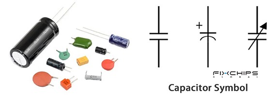
Types
- Ceramic Capacitor: Uses a ceramic material as its dielectric. It is commonly used for filtering, decoupling, and high-frequency circuits.
- Electrolytic Capacitor: Uses an oxide layer as its dielectric and an electrolyte as part of its structure. It provides high capacitance and is often used in power supplies.
- Film Capacitor: Uses a thin plastic film as its dielectric. It is commonly used in filtering, timing, and AC applications.
- Tantalum Capacitor: Uses tantalum oxide as its dielectric. It offers high capacitance in a compact size and is often used in small electronic devices.
Key Characteristics
The following specifications help describe a capacitor's electrical performance.
|
Specification |
Description |
|
Capacitance |
Measures how much electrical charge a capacitor can store per unit of voltage. It is measured in farads (F). |
|
Voltage Rating |
The maximum continuous voltage the capacitor is designed to withstand under specified conditions. |
|
Tolerance |
Shows how much the actual capacitance can differ from its stated value. |
|
Equivalent Series Resistance (ESR) |
Represents the internal resistance that causes energy loss and heat during operation. |
What Is an Inductor?
An inductor is a passive component that stores electrical energy in a magnetic field. It usually consists of a wire wound into a coil, with or without a magnetic core.
When current flows through the coil, it creates a magnetic field. The inductor opposes sudden changes in current and is commonly used in filters, power supplies, and electronic circuits.
Function
An inductor performs several functions in an electronic circuit:
- Energy Storage: Stores energy in its magnetic field and releases it when needed.
- Filtering: Blocks or reduces unwanted high-frequency signals in a circuit.
- Current Control: Opposes sudden changes in current to help keep current flow stable.
- Noise Suppression: Reduces unwanted electrical noise and interference.
- Power Conversion: Transfers and stores energy in switching power supplies.
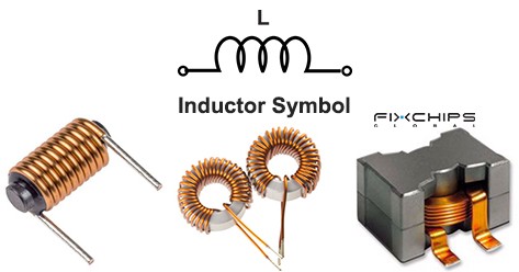
Types
- Air-Core Inductor: Uses air as its core material. It is often used in high-frequency and radio-frequency circuits.
- Iron-Core Inductor: Uses an iron-based magnetic core to increase inductance. It is commonly used in low-frequency power and filtering circuits.
- Ferrite-Core Inductor: Uses ferrite, a magnetic ceramic material, to guide the magnetic field. It is widely used in switching power supplies and high-frequency circuits.
Key Characteristics
The following specifications help describe an inductor's electrical performance.
|
Specification |
Description |
|
Inductance |
Measures how strongly an inductor opposes changes in current. It is measured in henries (H). |
|
Tolerance |
Shows how much the actual inductance can differ from its stated value. |
|
Rated Current |
The current the inductor can carry under specified temperature conditions. |
|
Self-Resonant Frequency (SRF) |
The frequency at which the inductor's inductance and internal parasitic capacitance resonate. |
|
DC Resistance (DCR) |
The resistance of the inductor's wire when DC flows through it. It affects power loss and heat generation. |
Capacitor vs Inductor: Structure
Although both components store energy, their internal structures are different. A capacitor uses conductive electrodes and an insulating layer, while an inductor mainly uses a coil of wire.
Structure of Capacitor
Most capacitors share two basic structural elements:
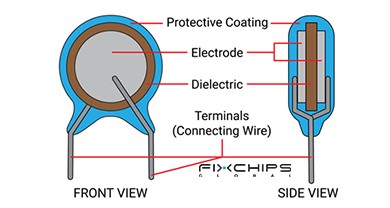
Electrodes: Two conductive parts that hold opposite electrical charges.
Dielectric: An insulating material between the electrodes that prevents direct current flow and stores energy in an electric field.
Structure of Inductor
Most inductors share the following basic structural elements:
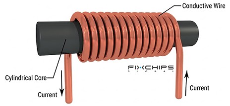
Coil: A length of conductive wire wound into turns to create a magnetic field when current flows.
Core: A material inside or around the coil that guides and strengthens the magnetic field. It may be air, iron, or ferrite.
Terminals: Conductive connections that allow the inductor to connect to an electronic circuit.
Capacitor vs Inductor: Working Principle
The main difference between these components is how they store energy. A capacitor uses an electric field, while an inductor uses a magnetic field.
How Does a Capacitor Work?
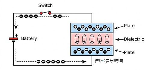
When a voltage source is connected, electrons build up on one electrode and leave the other. This creates an electric field between the electrodes and stores electrical energy in the dielectric.
When the capacitor is connected to a load, the stored energy can flow back into the circuit as the capacitor discharges.
How Does an Inductor Work?
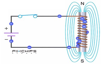
When current flows through the coil, it creates a magnetic field around the wire. This field stores energy and produces a voltage that opposes changes in current.
When the current decreases, the magnetic field collapses and releases its stored energy back into the circuit.
Capacitor vs Inductor in AC and DC Circuits
Capacitors and inductors respond differently to DC and AC because they react to changes in voltage and current.
In DC Circuit
- Capacitor: Allows current to flow while charging, then acts like an open circuit after reaching steady state.
- Inductor: Opposes changes in current during startup, then acts like a short circuit in an ideal steady-state DC circuit.
In AC Circuit
- Capacitor: Allows AC current to flow, with capacitive reactance decreasing as frequency increases.
- Inductor: Opposes AC current, with inductive reactance increasing as frequency increases.
For an ideal capacitor and inductor, their reactance can be calculated using:
Capacitive reactance:

Inductive reactance:

Here, f is frequency, C is capacitance, and L is inductance. Both reactance values are measured in ohms (Ω).
These relationships explain why capacitors and inductors are often used together in AC filters and frequency-selection circuits.
Capacitor vs Inductor: Applications
Capacitors and inductors are used in many electronic devices. However, their applications depend on how they store energy and respond to changes in voltage and current.
Applications of Capacitor
Capacitors are commonly used in the following applications:
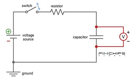
- Power Supplies: Smooth voltage changes and reduce ripple in power supply circuits.
- Electronic Filters: Remove unwanted signal frequencies from audio and communication circuits.
- Decoupling Circuits: Reduce voltage noise near integrated circuits (ICs).
- Camera Flash: Store electrical energy and release it quickly to produce a bright flash.
- Motor Circuits: Help create a phase shift for starting or running certain AC motors.
- Timing Circuits: Control charging and discharging time to set delays and timing intervals.
Applications of Inductor
Inductors are commonly used in the following applications:
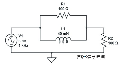
- Switching Power Supplies: Store and transfer energy during voltage conversion.
- EMI Filters: Reduce electromagnetic interference from unwanted electrical signals.
- Radio Frequency (RF) Circuits: Work with capacitors to select specific frequencies in radio circuits.
- Electric Motors: Help create magnetic fields that support motor operation.
- Transformers: Use magnetic coupling between coils to transfer electrical energy between circuits.
- Audio Equipment: Work in crossover circuits to direct different frequency ranges to suitable speakers.
Applications Using Both Capacitors and Inductors
Capacitors and inductors are often used together in electronic circuits. Their combined operation helps control voltage, current, and signal frequency.
Common applications include:
LC Filters
Combine an inductor and a capacitor to select or remove specific signal frequencies. They are widely used in radio receivers, audio circuits, and power supplies.
Switching Power Supplies
Use inductors to store and transfer energy, while capacitors smooth output voltage and reduce ripple. Both components help maintain a stable DC output.
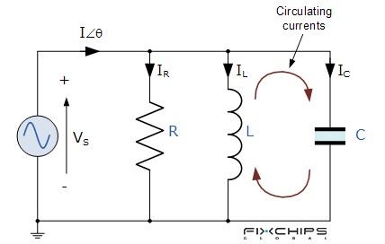
Resonant Circuits
Connect an inductor and a capacitor to create a resonant frequency. These circuits are commonly used in radio tuning, wireless power transfer, and signal processing.
EMI Filters
Combine inductors and capacitors to reduce unwanted electrical noise. They are commonly used in power input circuits to limit conducted interference.
DC-DC Converters
Use inductors to control energy transfer and capacitors to smooth input and output voltage. Both are important in buck and boost converter circuits.
In these applications, the inductor mainly controls changes in current, while the capacitor mainly controls changes in voltage. Working together, they help improve power stability and signal quality.
How to Choose Between Capacitor and Inductor
Choosing between a capacitor and an inductor depends on the circuit's purpose and operating conditions. The following table summarizes their main selection factors.
|
Selection Factor |
Choose a Capacitor When |
Choose an Inductor When |
|
Energy Storage |
need to store energy in an electric field. |
need to store energy in a magnetic field. |
|
Signal Filtering |
need to reduce low-frequency signals or pass high-frequency signals. |
need to reduce high-frequency signals or pass low-frequency signals. |
|
Voltage and Current Control |
need to smooth voltage changes and reduce ripple. |
need to limit sudden current changes and smooth current flow. |
|
Operating Frequency |
need lower reactance at higher frequencies. |
need higher reactance at higher frequencies. |
|
DC and AC Requirements |
need to block steady-state DC and allow AC signals to pass. |
need to pass steady-state DC and oppose sudden current changes. |
|
Circuit Design |
need a component for voltage stabilization, decoupling, or timing. |
need a component for current control, energy transfer, or magnetic field generation. |
Frequently Asked Questions
What is the primary function of an inductor?
An inductor stores electrical energy in a magnetic field and opposes sudden changes in current. It is commonly used in filters, power supplies, and noise reduction circuits.
Can an inductor pass AC current?
Yes. An inductor can conduct AC, but it opposes changes in current through inductive reactance. This opposition increases as the AC frequency rises.
Are inductors suitable for both AC and DC circuits?
Yes. Inductors are used in both AC and DC circuits. They oppose current changes in both types of circuits, but their steady-state behavior differs: an ideal inductor acts like a short circuit with DC and presents frequency-dependent reactance with AC.
Do capacitors block AC signals?
No. Capacitors generally block steady-state DC but allow AC signals to pass. Their capacitive reactance decreases as the signal frequency increases.
Can an inductor and capacitor work in the same circuit?
Yes. Inductors and capacitors are often connected together to form LC circuits. They are commonly used in filters, resonant circuits, and switching power supplies to control signal frequencies and manage electrical energy.
Which is more effective for reducing electrical noise: an inductor or a capacitor?
Both can reduce electrical noise, but they work in different ways. Inductors help block high-frequency noise, while capacitors provide a path for unwanted high-frequency signals; using both together in an LC filter can improve noise reduction.
Related Articles
Capacitor Symbol Guide - Types, Markings, and Uses
How to Choose the Right AC Capacitor? A Complete Guide
MLCC - Types, Electrical Properties, and Selection
What Is a Variable Capacitor? Types, Uses and Working Principle


