




Introduction
Modern electronic devices need stable power and clear signals to work properly. Smartphones, computers, cars, and industrial systems all use small components to control electrical changes.
One of these components is the Multilayer Ceramic Capacitor (MLCC). It helps stabilize voltage, reduce electrical noise, and support reliable circuit operation.
This guide explains how MLCCs work, what makes their types different, and how to choose the right component for your application.
What Is an MLCC Capacitor?
MLCC stands for Multilayer Ceramic Capacitor. It is a capacitor made from alternating layers of ceramic material and metal electrodes.
An MLCC stores electrical charge in an electric field. It can also help smooth voltage changes and reduce unwanted noise in a circuit.
MLCCs are widely used in consumer electronics, automotive systems, communication equipment, and industrial devices.
Their small size makes them suitable for printed circuit boards (PCBs) with limited space.
Main Functions of MLCCs
- Voltage stabilization: Helps reduce short-term voltage changes.
- Noise filtering: Helps remove unwanted electrical noise.
- Power supply decoupling: Helps keep the supply voltage stable near integrated circuits (ICs).
- Signal coupling: Allows AC signals to pass while blocking DC in suitable circuits.
- Energy storage: Stores and releases electrical charge as circuit conditions change.
How Does an MLCC Work?
To understand how an MLCC works, it helps to look at its internal structure.
MLCC Structure
An MLCC has several main parts.

- Ceramic dielectric layers: Insulating layers that separate the electrodes and affect capacitance.
- Internal electrodes: Thin metal layers that create an electric field when voltage is applied.
- External electrodes: Metal ends that connect the internal electrodes to the circuit.
- Protective body: The ceramic body surrounds and supports the internal layers.
The ceramic layers and metal electrodes are stacked together. This design provides a large effective electrode area in a small package.
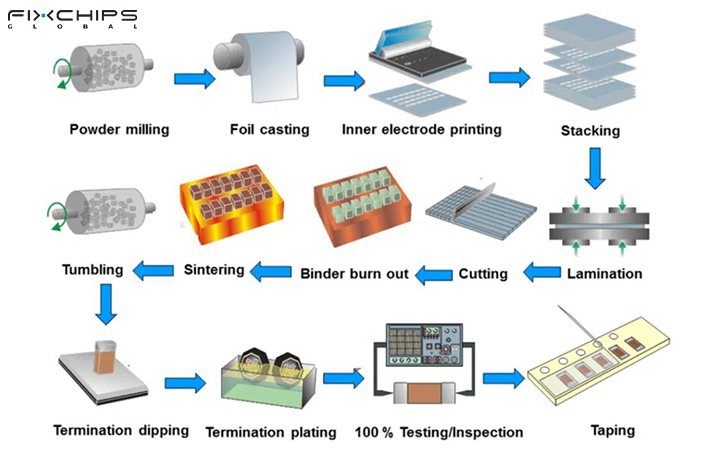
MLCC Manufacturing Process
The production of an MLCC involves several precise steps. Each step helps create a compact capacitor with the required electrical properties.
Working Principle
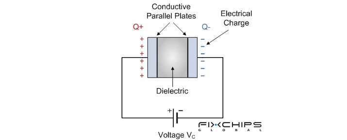
When a voltage is applied across an MLCC, an electric field forms between its internal electrodes.
The ceramic material separates the electrodes and allows the capacitor to store electrical charge. When the circuit voltage changes, the capacitor can charge or discharge.
For example, an MLCC placed near an IC power pin can supply a brief current when the local supply voltage drops. It can also help reduce high-frequency noise on the power line.
The capacitor does not create extra energy. It stores electrical energy and releases it when the circuit needs it.
MLCC Dielectric Material Classification
MLCCs are classified by the ceramic dielectric material inside them. The material affects capacitance, temperature stability, electrical loss, and response to applied voltage.
There are two main groups: Class I and Class II. Class I focuses on stability and low loss, while Class II provides higher capacitance in a smaller size.
Class I MLCC
Class I MLCCs are designed for circuits that need stable and accurate capacitance. Their dielectric materials are commonly based on titanium dioxide, with additives such as strontium titanate or calcium titanate to adjust their electrical properties.
Main Features:
- High stability: Capacitance changes very little with temperature.
- Low electrical loss: They dissipate little energy during operation.
- Low DC bias effect: Applied DC voltage causes very little capacitance change.
- Minimal aging: Capacitance remains stable over time.
- Good high-frequency performance: They suit circuits that require accurate capacitance and low loss.
Common Types: C0G/NP0

Common Applications:
- RF and high-frequency circuits
- Oscillators and timing circuits
- Precision analog circuits
- Signal filters and tuning circuits
- Measurement equipment
Class II MLCC
Class II MLCCs are designed to provide higher capacitance in a compact package. Their dielectric materials are mainly based on barium titanate, with additives that adjust temperature behavior and other electrical properties.
Main Features:
- High capacitance density: They provide more capacitance in a small space.
- Temperature-dependent capacitance: Capacitance changes within the specified operating temperature range.
- DC bias effect: Effective capacitance can decrease when DC voltage is applied.
- Aging effect: Capacitance gradually decreases over time.
Common Types: X7R, X5R, and Y5V

Common Applications:
- Power supply filtering and decoupling
- Smartphones, tablets, and laptops
- DC-DC converters and voltage regulators
- LED driver circuits
- Automotive and industrial electronic systems
Comparison of C0G/NP0, X7R, X5R, and Y5V
|
Comparison Feature |
C0G/NP0 |
X7R |
X5R |
Y5V |
| Classification | Class I | Class II | Class II | Class II |
|
Temperature Range |
-55°C to +125°C |
-55°C to +125°C |
-55°C to +85°C |
-30°C to +85°C |
|
Capacitance Change (Temperature) | ±30 ppm/°C | ±15% | ±15% |
+22% / -82% |
|
DC Bias Effect |
Negligible |
Can be significant |
Can be significant |
Often significant |
|
Aging Effect |
Negligible under normal conditions |
Present |
Present |
Present |
|
Dissipation Factor (tan δ) | ≤0.1% |
up to around 2.5% |
up to around 3.5% |
up to around 5% |
|
Piezoelectric Effect |
Negligible in normal use |
May be present |
May be present |
May be present |
|
Typical Applications |
RF, timing, oscillators, precision circuits |
Power filtering, decoupling, automotive electronics |
Compact power circuits, consumer electronics |
Cost-sensitive applications with less demanding stability needs |
Key Electrical Characteristics of MLCCs
The nominal capacitance printed in a product specification does not tell the whole story. Several other characteristics affect how an MLCC performs after it is installed.
Capacitance and Tolerance
Capacitance indicates how much electrical charge a capacitor can store at a given voltage.
It is usually measured in picofarads (pF), nanofarads (nF), or microfarads (μF).
There are three main factors that determine the capacitance of an MLCC.
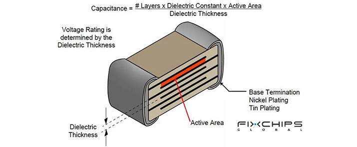
- Electrode area: A larger effective area generally increases capacitance.
- Distance between electrodes: A smaller distance generally increases capacitance
- Dielectric material: A material with a higher dielectric constant can provide greater capacitance for the same basic structure.
Tolerance shows how far the actual capacitance may differ from its specified nominal value under the stated test conditions.
For example, a 100 nF capacitor with a tolerance of ±10% has an allowed measured range of 90 nF to 110 nF under the applicable measurement conditions.
Circuits that require precise timing or frequency control may need tighter tolerance and better stability.
Rated Voltage and DC Bias
The rated voltage is the maximum specified DC voltage under the manufacturer's stated operating conditions.
Common MLCC ratings include 6.3 V, 10 V, 16 V, 25 V, and 50 V, with other ratings also available.
Engineers must check both the rated voltage and the effective capacitance at the actual operating voltage.
For many Class II MLCCs, capacitance decreases as DC bias increases. The amount of change depends on the specific component design.
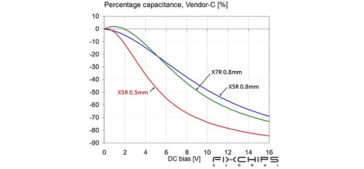
For example, a nominal 10 μF MLCC may provide less than 10 μF when operating under DC voltage. The actual value must be checked using the manufacturer's DC-bias data.
A higher rated voltage alone does not guarantee a particular effective capacitance. The full datasheet is still needed.
Temperature Characteristics
Temperature can change the capacitance of an MLCC.
C0G/NP0 provides high temperature stability. X7R and X5R allow greater capacitance changes but offer higher capacitance density.
For general power filtering, an X7R or X5R component may be suitable. For circuits that need stable timing or frequency response, C0G/NP0 may be a better choice.
ESR, ESL, and Frequency Response
ESR and ESL affect how an MLCC behaves as the signal frequency changes.
Low ESR helps reduce resistive losses. Low ESL helps the capacitor respond more effectively to high-frequency changes.
However, an MLCC does not behave as an ideal capacitor at every frequency. Each part has a self-resonant frequency.
Below this frequency, capacitive behavior dominates. Above it, parasitic inductance becomes more important.
For this reason, engineers should consider impedance curves and the intended frequency range rather than choosing a capacitor by capacitance alone.
Common MLCC Package Sizes
Package size describes the physical dimensions of an MLCC. Common EIA inch-code sizes include 0201, 0402, 0603, 0805, and 1206.
|
MLCC Package Size |
Dimensions (L × W) |
Capacitance Capability |
Mounting Difficulty |
Relative Cost |
Typical Applications |
|
0201 (0603 Metric) |
0.6 × 0.3 mm |
Lowest |
★★★★★ Very Difficult
|
★★★★★ Highest |
Smartphones, wearable devices, RF modules, miniaturized electronic products |
|
0402 (1005 Metric) |
1.0 × 0.5 mm |
Low to medium |
★★★★ Difficult |
★★★★ Higher |
Mobile devices, IoT products, Bluetooth modules, IC decoupling |
|
0603 (1608 Metric) |
1.6 × 0.8 mm |
Medium |
★★★ Moderate |
★★★ Medium |
Consumer electronics, automotive electronics, general-purpose circuits |
|
0805 (2012 Metric) |
2.0 × 1.25 mm |
Medium to high |
★★ Easy |
★★ Lower |
Power filtering, industrial equipment, power supply circuits |
|
1206 (3216 Metric) |
3.2 × 1.6 mm |
High |
★ Easy |
★★ Lower |
Automotive electronics, DC/DC converters, industrial control systems |
|
1210 (3225 Metric) |
3.2 × 2.5 mm |
Very high |
★ Easy |
★ Low |
Power management systems, high-current circuits, energy storage applications |
|
1812 (4532 Metric) |
4.5 × 3.2 mm |
Higher |
★ Easy
|
★ Low |
High-voltage circuits, industrial equipment, power electronics |
|
2220 (5750 Metric) |
5.7 × 5.0 mm |
Highest |
★ Easy
|
★ Low |
High-voltage systems, industrial power equipment, automotive applications |
Main Applications of MLCCs
MLCCs appear in many electronic products because they combine small size with useful electrical performance.
Consumer Electronics
Smartphones, laptops, tablets, and wearable devices use MLCCs in power supply and signal circuits. Their small packages help manufacturers fit more functions into limited space.
Automotive Electronics
Vehicles use MLCCs in control units, sensors, communication systems, and power circuits. The selected component must meet the temperature, voltage, and reliability requirements of its location.
Industrial Equipment
Industrial controllers, power supplies, and measurement systems use MLCCs for filtering and decoupling. Component selection depends on operating conditions and circuit requirements.
Communication Equipment
Wireless modules and other communication systems use suitable MLCCs for signal coupling, filtering, and RF circuits. Stable dielectric types may be needed when capacitance accuracy is important.
Pros and Cons of MLCCs
MLCCs are popular because they offer several useful electrical and physical properties. However, their performance also has limits.
Main Advantages
- Small size: Multiple internal layers allow high capacitance in a compact package. This is useful for mobile devices and other products with limited PCB space.
- Low ESR and ESL: Equivalent Series Resistance (ESR) represents internal resistive losses. Equivalent Series Inductance (ESL) represents unwanted inductance. Both affect how a capacitor performs in a real circuit.
- Good high-frequency performance: Many MLCCs respond well to high-frequency signals and noise. This makes them useful for decoupling and filtering near ICs.
- Wide range of options: MLCCs are available in different capacitance values, voltage ratings, dielectric types, and package sizes.

Main Limitations
- Capacitance can change: Some MLCC types lose capacitance when DC voltage is applied. Temperature and aging can also affect their performance.
- Mechanical stress can cause damage: The ceramic body is brittle. Excessive PCB bending or assembly stress can cause cracks.
- Circuit behavior may change: Very low ESR and parasitic inductance can affect the stability or frequency response of some circuits.
How to Choose the Right MLCC
Selecting an MLCC requires more than matching the capacitance value. The following steps help narrow down the right part.
Step 1: Identify the Application
Determine whether the MLCC is used for power supply decoupling, noise filtering, signal coupling, timing, or another purpose.
Different functions may require different electrical characteristics.
Step 2: Select the Dielectric Type
Choose C0G/NP0 when high stability and low loss are important.
Choose X7R or X5R when higher capacitance in a small package is the main goal. Consider the capacitance changes caused by voltage and temperature.
Step 3: Check Capacitance and Tolerance
Confirm the nominal capacitance and allowed tolerance.
For Class II MLCCs, also check the effective capacitance under the expected DC voltage and operating temperature.
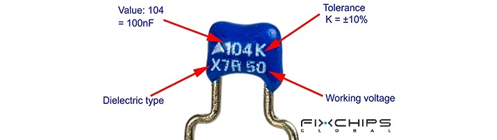
Step 4: Confirm the Voltage Rating
Make sure the selected component meets the circuit's voltage requirements, including relevant transient and AC conditions.
Do not operate the component beyond its specified limits. Follow the manufacturer's recommendations for voltage and temperature.
Step 5: Choose the Package Size
Check the available PCB space and assembly process.
Also consider the risk of mechanical stress. In some applications, a suitable flexible-termination design may help reduce the risk of damage caused by board flex.
Step 6: Review the Datasheet
Before final selection, check the following information:
- Rated voltage and capacitance tolerance
- DC-bias characteristics
- Temperature range
- ESR, ESL, and impedance curves
- Aging characteristics
- Package dimensions and reliability qualifications
For automotive or industrial applications, confirm that the component meets the required industry and application standards.
Frequently Asked Questions
What does MLCC stand for?
MLCC stands for Multilayer Ceramic Capacitor. It uses stacked ceramic dielectric layers and metal electrodes to store electrical charge in a compact package.
What is the main function of an MLCC?
An MLCC commonly helps stabilize voltage and reduce electrical noise. Depending on the circuit, it can also support signal coupling, filtering, and energy storage.
What is the difference between C0G and X7R MLCCs?
C0G provides highly stable capacitance and low electrical loss. X7R offers higher capacitance density but is more affected by applied voltage, temperature, and aging.
Why does an MLCC lose capacitance under DC voltage?
Some Class II MLCCs experience a DC-bias effect. Their effective capacitance decreases as the applied DC voltage increases, and the amount of change depends on the specific component.
Are larger MLCC packages always better?
No. Larger packages may support different capacitance and voltage options, but size alone does not determine performance. The best package must meet the circuit's electrical, mechanical, and space requirements.
What are MLCCs commonly used for?
MLCCs are used in smartphones, computers, automotive electronics, industrial equipment, and communication devices. Common functions include power supply decoupling, noise filtering, and signal coupling.
Related Articles
What Is a Variable Capacitor? Types, Uses and Working Principle


