




A resistor symbol is a simple drawing used to represent a resistor in a circuit diagram. It shows where the component is placed and how it connects to other parts of the circuit.
This guide shows what resistor symbols mean, the common resistor symbol types, the differences between ANSI and IEC symbols, how to identify resistor symbols in circuit diagrams and avoid mistakes when reading a circuit schematic.
What Is a Resistor?
A resistor is a passive electronic component that opposes the flow of electric current. Its resistance is measured in ohms (Ω).
In a circuit, a resistor can limit current, divide voltage, and help set the operating conditions of other components.
Therefore, resistors are used in many electronic devices, from simple control circuits to computers and consumer electronics.
What Is a Resistor Symbol?
A resistor symbol is a standard graphic used to represent a resistor in a circuit or schematic diagram. It shows the component's electrical role rather than its physical appearance.
International Standards
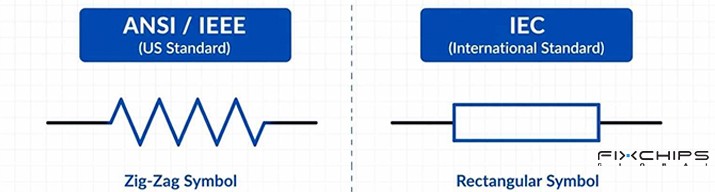
Resistor symbols can look different across circuit diagrams. Two commonly encountered drawing conventions are associated with ANSI/IEEE standard and IEC standard.
The American-style zigzag symbol and the IEC-style rectangular symbol represent the same basic component. Knowing both forms helps when reading diagrams from different sources.
|
Feature | ANSI/IEEE Standard | IEC Standard |
|
Basic shape |
Zigzag line |
Rectangle |
| Region | North America | Europe, Asia, International |
|
Reference |
IEEE Std 315 |
IEC 60617 |
Common Resistor Symbols
Fixed Resistor
A fixed resistor has a specified resistance value that is not normally adjusted during operation.
Its symbol has no adjustment arrow. Depending on the drawing convention, it appears as a zigzag line or a rectangle.
Common fixed resistor types include carbon composition, wire-wound, thick-film, thin-film, and Metal oxide film resistors. Their construction differs, but the basic circuit symbol may be the same.
Common fixed resistor comparison
|
Resistor Type | Symbol |
Construction |
Main Function |
|
Carbon Composition Resistor |
|
Carbon powder mixed with a binder and pressed into a solid body. |
Limits current and handles short current surges in pulse circuits. |
|
Wire-Wound Resistor |
|
Resistance wire wound around a ceramic core. |
Handles high power and limits large currents in power circuits. |
|
Thick-Film Resistor |
|
Resistive paste printed onto a ceramic base. |
Limits current and sets voltage levels in common electronic devices. |
|
Thin-Film Resistor |
|
A thin resistive layer deposited on a ceramic base. |
Provides precise resistance for signal processing and measurement circuits. |
|
Metal Oxide Film Resistor |
|
Metal oxide film coated on a ceramic core. |
Limits current in circuits exposed to high heat or voltage stress. |

Variable Resistor
A variable resistor allows its effective resistance to be changed. This is usually done by moving a contact along a resistive element.
Its symbol adds an arrow or movable-contact mark to the basic resistor shape. This extra mark helps distinguish it from a fixed resistor.
 Common examples include potentiometers and preset resistors.
Potentiometer
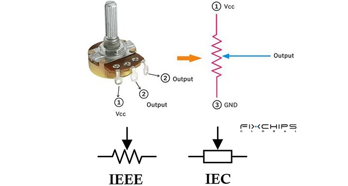
A potentiometer is a three-terminal adjustable resistor. Its movable contact, called a wiper, changes the resistance between the wiper and each end of the resistive element. Potentiometers are often used to adjust settings such as volume or control level.
The symbol usually shows a resistor with an arrow pointing toward the resistive element. The arrow represents the movable wiper.
 Preset Resistor
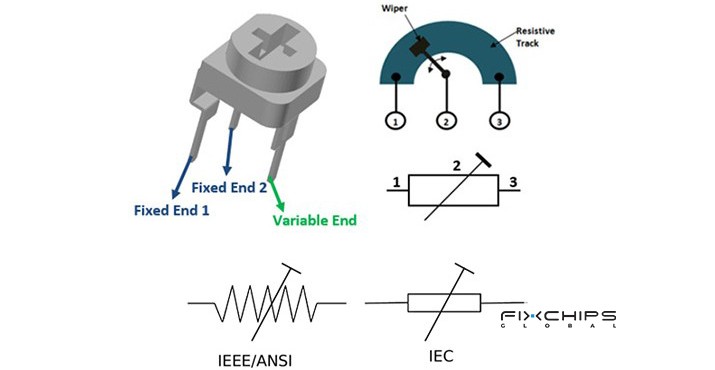
A preset resistor, also called a trimmer, is designed for adjustment during manufacturing, testing, or servicing. It is not usually intended for frequent user adjustment.
Its symbol indicates an adjustable resistance. The exact appearance depends on the drawing convention and the type of component.
Special Resistor Symbols
Some resistors change their behavior when voltage, temperature, or light changes. These components are often called non-linear resistors because their resistance does not remain constant under all operating conditions.
Their symbols use the basic resistor form with additional markings. The markings help show which condition affects the component.
Thermistor
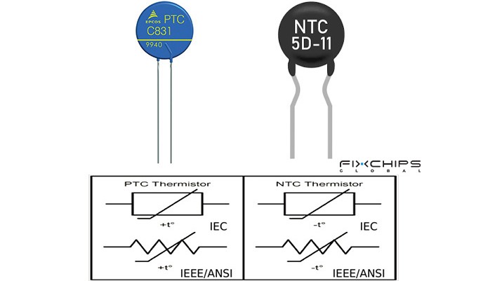
A thermistor is a resistor whose resistance changes with temperature. The two common types are NTC and PTC thermistors.
- NTC: Resistance generally decreases as temperature rises.
- PTC: Resistance generally increases as temperature rises over its specified operating range.
A thermistor symbol adds a diagonal line with a bent end to the resistor shape. The nearby label or circuit notes may help identify whether it is NTC or PTC.
 Varistor Symbol
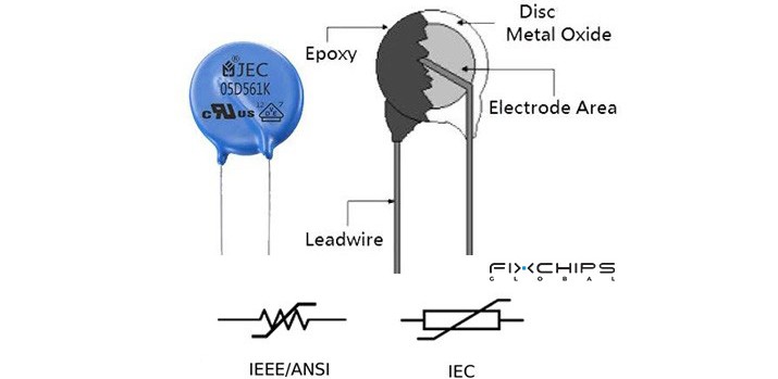
A varistor is also known as a voltage-dependent resistor (VDR). Its resistance changes according to the voltage across it. A metal oxide varistor (MOV) is a common type. Varistors are often used to help protect circuits from voltage surges.
A varistor symbol features a diagonal line bent at both ends passing through the resistor.
 Light-Dependent Resistor Symbol
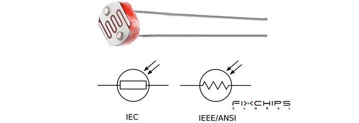
A light-dependent resistor (LDR), also called a photoresistor, changes its resistance according to the light reaching its surface.
It can be used in circuits that respond to changes in light level. For example, an LDR can provide an input to a light-sensitive control circuit.
Its symbol commonly shows arrows pointing toward the resistor to represent incoming light.
 Resistor Quick Lookup Table
|
Component |
What Changes? |
Main Purpose |
|
Fixed resistor |
Resistance is normally set |
Current limiting and voltage division |
|
Variable resistor |
Resistance can be adjusted |
Circuit adjustment |
|
Thermistor |
Temperature affects resistance |
Temperature sensing and control |
|
Varistor |
Voltage affects resistance |
Voltage surge protection |
|
LDR |
Light affects resistance |
Light detection |
How to Identify a Resistor in a Schematic
You can use a simple process when reading an unfamiliar circuit diagram.
|
Step |
What to Check |
Why It Matters |
|
1. Find the shape |
Look for a zigzag line or rectangle |
Helps identify a possible resistor |
|
2. Read the label |
Check for R1, R2, or a similar reference |
Links the symbol to the component list |
|
3. Check the value |
Look for Ω, kΩ, or MΩ |
Shows the stated resistance |
|
4. Follow the wires |
Trace the connected circuit paths |
Helps explain the resistor's role |
|
5. Check extra marks |
Look for arrows or condition-related markings |
May indicate a special resistor |
|
6. Confirm the details |
Read the legend or parts list |
Helps resolve unclear symbols |
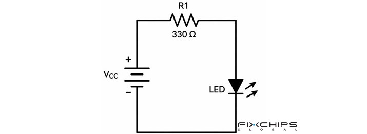
For example, look the picture below, it is a circuit containing an LED and a resistor labeled R, with a value of 330 Ω. Following the steps, we can conclude the role of the fixed resistor is to limit the current flowing through the LED.
 Common Mistakes When Reading Resistor Symbols
Even a simple symbol can cause confusion if you rely on its shape alone.
- Treating the zigzag and rectangle as different components
Both shapes can represent a resistor. The difference usually comes from the drawing convention.
- Assuming every resistor has a fixed value
Some resistors are adjustable. Others change resistance in response to temperature, voltage, or light. Look for additional marks and read the component label before deciding which type is shown.
- Confusing the symbol with the physical component
A circuit symbol is a simplified graphic. It does not normally show the resistor's exact size, material, package, or power rating. Use the parts list or technical specification when these details matter.
- Ignoring the resistance value
The symbol shows the component type, but it does not necessarily tell you its resistance. Check the value beside the symbol or in the component list before using the circuit information.
Resistor Symbols vs. Other Component Symbols
Resistor symbols can be confused with other component symbols when you first read a circuit diagram. Comparing their shapes and functions makes them easier to tell apart.
Resistor vs. Capacitor
A resistor is usually shown as a zigzag line or rectangle. A capacitor is commonly shown as two plates separated by a gap.
A resistor provides resistance to current. A capacitor stores energy in an electric field and can affect how a circuit responds to changing voltage.
Resistor vs. Inductor
A resistor uses a zigzag or rectangular shape. An inductor is usually drawn as a coil or a series of loops.
A resistor can limit current and create a voltage drop. An inductor stores energy in a magnetic field and responds to changes in current.
Resistor, Capacitor, and Inductor Symbol Comparison
|
Component |
Common Symbol Shape |
Main Function |
Common Uses |
|
Resistor |
Zigzag line or rectangle |
Provides resistance |
Current limiting and voltage division |
|
Capacitor |
Two separated plates |
Stores energy in an electric field |
Filtering, coupling, and timing |
|
Inductor |
Coil or loops |
Stores energy in a magnetic field |
Filtering and magnetic coupling |
Frequently Asked Questions
What are the two common resistor symbols?
The two common forms are a zigzag line and a rectangle. The zigzag form is widely used in American-style diagrams, while the rectangle is common in IEC-based diagrams.
How is a variable resistor shown in a circuit?
A variable resistor symbol usually includes an arrow or movable-contact mark. This indicates that the resistance can be adjusted.
How do you find a resistor in a circuit diagram?
Look for a zigzag or rectangular shape, then check its reference label, such as R1 or R2. Follow the connecting wires and check the stated resistance value to understand its role.
Can a resistor symbol show the exact component type?
Not always. Different fixed resistors may share the same basic symbol, and special resistor symbols can vary by drawing convention. Check the circuit legend or component specification when the exact type matters.
What is the difference between resistor and capacitor symbols?
A resistor is commonly shown as a zigzag line or rectangle, while a capacitor is represented by two separated plates. A resistor provides resistance, while a capacitor stores energy in an electric field.
What does a resistor do in a circuit?
A resistor opposes the flow of electric current. It is commonly used to limit current, divide voltage, and set operating conditions for other components.
Related Articles
Exploring Variable Resistor’s Types, Functions and Uses


