




Introduction
A rectifier diode allows current to flow mainly in one direction. It is widely used to convert alternating current (AC) into direct current (DC).
This guide explains how rectifier diodes work, compares their main types, and shows how to choose, test, and maintain them.
What Is a Rectifier Diode?
A rectifier diode is a semiconductor device with two terminals: an anode and a cathode. It allows current to pass when connected in the correct direction and blocks most current when the voltage is reversed.
Most common rectifier diodes use silicon as material. Inside the diode, a semiconductor junction controls the flow of electric current. The diode does not create energy. Instead, it controls which parts of an AC signal can pass through a circuit.
Rectifier diodes are used in power supplies, battery chargers, home appliances, and industrial equipment. They help turn AC from a power source into pulsating DC, which can then be smoothed by capacitors or other filter circuits.
Function
The main functions of a rectifier diode include:
- AC-to-DC conversion: It passes one direction of current to produce a DC output.
- One-way current control: It allows current to pass mainly in the forward direction.
- Reverse voltage blocking: It limits current when reverse voltage is applied, within its rated limits.
- Power supply control: It works with other components to provide power to electronic devices.
How Does a Rectifier Diode Work?
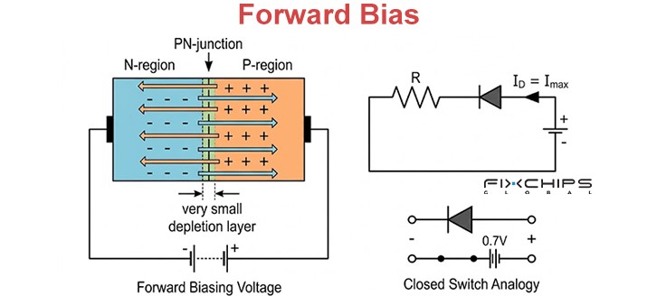
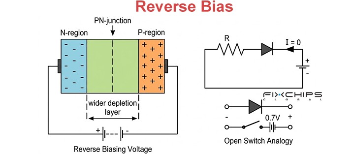
A common silicon rectifier diode has a P-type region and an N-type region. The boundary between them is called a PN junction. This junction creates a barrier that controls current flow.
When a suitable forward voltage is applied, the barrier becomes easier to cross, and current flows. When the voltage is reversed, the barrier becomes wider, and only a small leakage current normally flows.
Forward Bias
When the anode is connected to a higher potential than the cathode, the diode is forward-biased. Once the applied voltage is sufficient, current flows through the junction.
For a silicon diode, the forward voltage drop is often around 0.6–0.7 V at modest current levels. This is only a general guide; the actual value depends on current, temperature, and the specific device.
Reverse Bias
When the anode is at a lower potential than the cathode, the diode is reverse-biased. The depletion region widens, so only a small leakage current normally flows.
If the reverse voltage exceeds the diode's breakdown rating, a large current may flow and damage a standard rectifier diode. Some specially designed diodes are made to operate in breakdown, but standard rectifier diodes should not be used this way.
Comparison of the Three Operating States
Two Types of Rectifier Circuits
Rectifier circuits are commonly divided into half-wave and full-wave types. They differ in how much of the AC input they use.
Half-Wave Rectifier Circuit
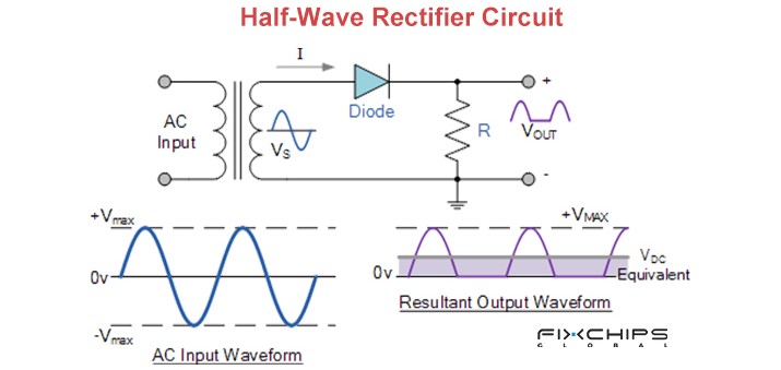
A half-wave rectifier usually uses one diode. During one half-cycle of the AC input, the diode is forward-biased and allows current to reach the load. During the opposite half-cycle, it blocks most of the current.
This circuit is simple, inexpensive, and easy to build. However, it uses only one half of the input waveform. Its output has more gaps and ripple, so it is less suitable when a smooth DC supply is needed.
Full-Wave Rectifier Circuit
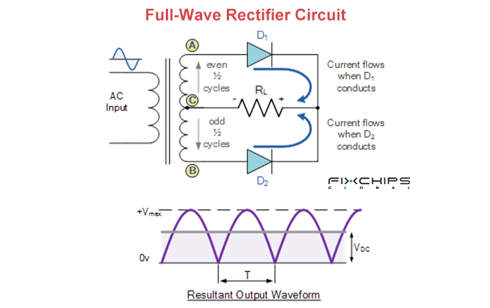
A full-wave rectifier uses both halves of the AC waveform. A bridge rectifier commonly uses four diodes arranged so that the current through the load keeps the same direction during both half-cycles. Another design uses two diodes with a center-tapped transformer.
Full-wave rectification provides a more frequent series of output pulses than half-wave rectification. This makes the output easier to smooth with a filter. However, a bridge circuit has two diodes conducting at the same time, so their forward voltage drops affect power loss.
Half-Wave vs. Full-Wave Rectification
|
Comparison |
Half-Wave |
Full-Wave |
|
Common diode arrangement |
One diode |
Four diodes in a bridge, or two with a center tap |
|
AC input used |
One half-cycle |
Both half-cycles |
|
Output pulses |
One pulse per AC cycle |
Two pulses per AC cycle |
|
Output ripple |
Higher before filtering |
Lower before filtering |
|
Circuit complexity |
Low |
Higher |
|
Common use |
Simple, low-cost circuits |
DC power supplies and chargers |
Parameters of Rectifier Diodes
A diode's datasheet lists its electrical and thermal limits. Check these values before using a diode in a circuit.
|
Parameter |
Symbol |
Meaning |
|
Average forward current |
IF(AV) |
The average current the diode can carry under specified cooling and operating conditions |
|
Repetitive peak reverse voltage |
VRRM |
The highest repeated reverse-voltage peak allowed under the stated conditions |
|
Forward voltage |
VF |
The voltage drop across the diode while it conducts |
|
Reverse recovery time |
trr |
The time needed to stop conducting after switching from forward current to reverse bias |
|
Surge forward current |
IFSM |
The permitted peak forward current for a short, specified surge |
|
Junction temperature |
TJ |
The temperature limit of the semiconductor junction |
|
Reverse leakage current |
IR |
The small current that flows under reverse bias |
Note: These parameters do not have one fixed value for all rectifier diodes. For example, a small signal diode and a high-current power diode can have very different current ratings. Always check the test conditions in the datasheet.
Types of Rectifier Diodes
Rectifier diodes are designed for different needs, such as low power loss, fast switching, high current, or a specific voltage function.
Standard Diode
A standard rectifier diode commonly uses a silicon PN junction. It is suitable for many low-frequency AC-to-DC circuits, such as basic power supplies. Its switching speed may be too slow for some high-frequency circuits.
Fast Recovery Diode
A fast recovery diode is designed to stop conducting more quickly after forward current ends. It is useful in switching power supplies, converters, and other circuits where slow recovery can increase switching losses.

Schottky Diode
A Schottky diode uses a metal-semiconductor junction rather than a standard PN junction. It often has a lower forward voltage drop and very fast switching, making it useful in low-voltage power supplies. However, its reverse leakage and reverse-voltage ratings must be checked carefully.

Zener Diode
A Zener diode is designed to operate in reverse breakdown at a specified voltage. It is commonly used for voltage reference and simple voltage regulation. It is not a direct replacement for a standard rectifier diode because its main purpose is different.

High-Current Diode
A high-current diode is built to carry larger currents than small general-purpose parts. Its construction and package are designed to manage heat and electrical stress. It is used in power converters, industrial power systems, and battery charging circuits.

Bridge Rectifier
A bridge rectifier is an arrangement of four diodes in one full-wave rectifier circuit, often sold as a single component. It converts both halves of an AC waveform into a pulsating DC output. The bridge must be selected for the required current, reverse voltage, and heat dissipation.

How to Choose the Right Rectifier Diode
Choosing a suitable rectifier diode helps reduce overheating, unwanted power loss, and early failure. Check the circuit requirements before selecting a part.
- Check the reverse voltage
Choose a diode with a repetitive peak reverse-voltage rating above the highest expected reverse voltage. Allow suitable margin for voltage spikes and other circuit conditions.
- Check the forward current
Confirm the average and peak current the circuit will require. The diode's rated current must suit the actual operating conditions, not just the nominal load value.
- Review the forward voltage
A lower forward voltage can reduce power loss, especially in low-voltage, high-current circuits. Compare the datasheet values at the current you expect to use.
- Consider switching speed
For low-frequency mains rectification, a standard diode may be suitable.
For high-frequency switching, check reverse recovery time and consider a fast recovery or Schottky diode where appropriate.
- Check the temperature limits
Review the maximum junction temperature and the thermal resistance of the package. Add suitable cooling if the expected power loss would cause excessive heat.
- Check surge-current capability
Power-on events and sudden changes in load can create short current peaks. Make sure the diode's surge rating and specified waveform match the circuit's expected stress.
- Confirm package and mounting needs
Check the pin layout, anode and cathode markings, board space, and heat-sink requirements. The selected diode must fit the circuit and allow safe heat removal.
How to Test a Rectifier Diode with a Multimeter
A digital multimeter with a diode-test mode can help check whether a diode conducts in one direction and blocks in the other. For a reliable result, switch off the power and discharge capacitors before testing.
|
Step |
What to Do |
Tip |
|
1. Turn off power |
Disconnect the circuit from its power source. |
Never test resistance or diode mode on a live circuit. |
|
2. Discharge capacitors |
Safely discharge capacitors and confirm that no dangerous voltage remains. |
Follow the equipment's safety instructions. |
|
3. Isolate the diode |
Remove the diode or disconnect at least one lead when possible. |
Other components can affect the reading. |
|
4. Select diode mode |
Set the multimeter to its diode-test function. |
Check the meter manual if the symbol is unclear. |
|
5. Test forward bias |
Place the red probe on the anode and the black probe on the cathode. |
A silicon diode often shows a forward drop near 0.6–0.7 V. |
|
6. Reverse the probes |
Place the red probe on the cathode and the black probe on the anode. |
A good standard diode normally shows OL or a very high reading. |
|
7. Read the results |
Compare the two readings and check for an open or short circuit. |
A low reading in both directions may indicate a short; OL in both directions may indicate an open diode |
How to Maintain Rectifier Diodes
Good circuit design and regular checks can reduce heat stress and help rectifier diodes work reliably.

- Control operating temperature: High junction temperatures can shorten service life, so provide suitable ventilation, heat sinks, or other cooling when needed.
- Stay within rated limits: Keep forward current and reverse voltage within the datasheet limits.
- Allow for voltage spikes: Use suitable circuit protection when surges or switching transients are expected.
- Check solder joints and connections: Loose or damaged connections can cause extra resistance and local heating.
- Keep the circuit clean and dry: Dust, moisture, and contamination can affect insulation and increase the risk of unwanted current paths.
- Inspect for damage: Look for cracks, discoloration, melted packages, or signs of overheating, and investigate the cause before replacing a failed part.
- Use proper thermal design: Check the diode's power loss and thermal path under the real load, rather than relying only on its headline current rating.
Applications of Rectifier Diode
Rectifier diodes are used wherever a circuit needs to direct current or convert AC into DC.
- Power supplies
- Battery chargers
- Consumer electronics
- Automotive systems
- Industrial equipment
- Solar power systems
- Inductive-load circuits
- Welding and power conversion
Frequently Asked Questions
How is a rectifier different from a diode?
A diode is an electronic component that allows current to flow mainly in one direction. A rectifier is a device or circuit that converts AC into DC, often by using one or more diodes.
What is the main purpose of a rectifier diode?
A rectifier converts alternating current (AC) into direct current (DC). It uses diodes to block or redirect part of the AC waveform, producing a DC output that can be smoothed by a filter.
Is it safe to connect a rectifier diode in reverse?
A standard rectifier diode can block current when reverse voltage is applied, but only within its rated reverse-voltage limit. If the voltage exceeds this limit, the diode may enter breakdown and become damaged.
Can high temperature change rectifier diode performance?
Yes. Temperature affects a diode's forward voltage, leakage current, and ability to handle power. Excessive heat can damage the diode, so keep its junction temperature within the limits stated in the datasheet.
Is it possible to use several rectifier diodes in one circuit?
Yes. Multiple diodes can be arranged in a bridge rectifier to convert both half-cycles of AC into pulsating DC. Other circuits may use several diodes for voltage blocking or protection, but their arrangement and ratings must match the circuit's needs. Source: Analog Devices
What is the correct way to check a rectifier diode?
Turn off the power, safely discharge any capacitors, and set a digital multimeter to diode-test mode. A working standard silicon diode usually shows a forward voltage drop in one direction and an OL reading in the reverse direction.
Related Articles


